DV-IN
CONTENTS| JVC CAMS |
| PANASONIC CAMS |
JVC CAMCORDERS
(especially the DVLx00 series)
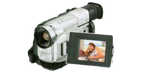
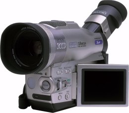
Some features of the JVC GR-DVL100E
| Digital recording (miniDV format), |
| Nice image with LOW light, |
| Awsome image quality with good lighting (better than many professional cameras), |
| 1/4" CCD with 800.000 pixels (PAL version), |
| 10x/100x (Optical/Digital) ZOOM, |
| 2.5" color LCD display, |
| Transfer of digital stills to a computer, |
| Connection to a Personal Computer (RS-232 and DV/IEEE 1394 card), |
| Lots of effects (fading and others), |
| 1 flaw: Image stabilizer is Digital, and |
| 1 disadvantage: there are no zoom lenses available. |
How to use DV-in
| In order to use DV-in you must connect the DV cable BEFORE powering on the camera. Otherwise the camera wouldn't accept any signal from the DV port. For some camera models you have to press the REC button twice, one to show DV-in on the LCD and other to start recording. |
| You have to put the camera in PLAY mode and press the REC to start recording from the DV-in port. |
| It is also NOT possible to see what you are recording on the TV through the AV cable but only on the camera's LCD screen. |
Important Notices
| When I write that a certain model is supported its because at least TWO JVCEM users confirmed it to be working with that model. If it is not working for you it's because you ARE doing something wrong or there is some incompatibility between your DV-card+drivers and camera. |
| For more recent JVC cameras it appears that DV-in enabling is no longer possible. At least JVCEM users keep complaining and asking for help on models listed as supported. I did what I could to help you out (I wrote JVCEM) so please DON'T complain to me or to any of JVCEM translators. If you feel the need to complain, do it to JVC not to someone who is doing something the best they possibly can. |
| If your model is not listed as supported I CAN'T pomise DV-in enabling will be possible. |
| As for most people in the world, time is precious and this is a non-profitable project. So, I will OLNY answer selected mail not concerning: |
| - JVCEM problems covered in the ducumentation (wich seems to be quite reasonable according to most people), |
| - JVC camera capabilities (ask JVC for support), |
| - Problems with DV transfer (ask a vendor or manufacturer for support), |
| - What is DV-in, |
| - Any other question I don't feel myself obligated to answer. |
JVC EEPROM Manager
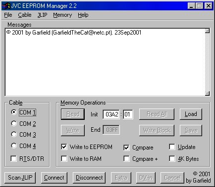 |
| The JVC EEPROM Manager 2.2 for JVC/Thomson miniDV cameras is a program that supports DV-in enabling/disabling the models listed bellow as working but it might work others. It works by changing a bit on the camera's EEPROM so, if your model isn't supported by the Enable/Disable button you can enable DV-in if you know what bit needs to be changed. |
| The program is also able to read and write ANY byte of the EEPROM on any JLIP compatible camera and that is the reason I named it "JVC EEPROM Manager". |
| Among other features JVCEM only takes 50Kb of disk space and it can save and load the contents of the EEPROM to and from a file. |
| Writing of memory values should be used with care because it can be dangerous (You might think your camera needs a service repair) |
| Read JVC.txt of the most recent version. |
| NOTE: The most recent beta version is available at the Download section. |
| NOTE: Thomson VMD2 and VMD3 are equivalente to JVC DVL20 and DVL40 respectively |
| NOTE: Thomson VMD10 is equivalente to JVC DVL970 |
| JLIP Debugger |
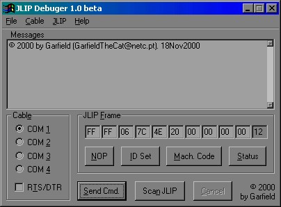 |
| Soon I will put here a program to send JLIP commands to ANY JLIP (or JLIP compatible) device. This program will allow you to have low level access to <BZANYJLIP (or JLIP compatible) device. |
Compatibility list (for DV-in enabling with JVCEM)
| The JVC miniDV models that are confirmed to be supported are: |
| - GR-DVL20E, GR-DVL30E, GR-DVL40E, GR-DVL100E, GR-DVL108E, GR-DVL150E, GR-DVL200E, GR-DVL300E, GR-DVL308E, GR-DVL450E, GR-DVL9200E, GR-DVL9500E, GR-DVL9700E, GR-DVX4E, GR-DVX7E, GR-DVX8E, GR-DVX9E, GR-DVx44E. |
| The confirmed Thomson miniDV models are: |
| - VMD2, VMD3, VMD8, VMD10. |
Incompatibility list (for DV-in enabling with JVCEM)
| It is not possible to enable DV-in on JVC GR-DVL9000, GR-DV3, GR-DVXEG and GR-DVM5. For these models the DV microprocessor supports DV-out ONLY (thanks Michel). |
The cables
| If you have an original JLIP cable to transfer still pictures you can use it in the same configuration as the JLIP software. Otherwise you can build your own cable at home. |
| There are two types of cables for JVC cameras. The 2.5mm 3-pole cable that is connected to the plug labeled (PC) Digital Still and the 3.5mm 4-pole cable that is conencted to the plug labeled JLIP. Both cables have the same functionalities but are used on different camera models. |
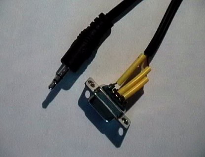
| The 2.5mm 3-pole |
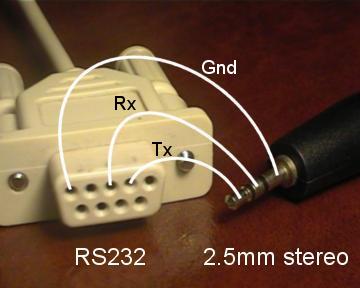 |
| As you can see from the fabulous picture above, the 2.5mm cable is VERY simple. All you need is a 2.5mm stereo jack (for the camera), a RS-232 plug (from a broken mouse, for example) and some soldering skills. For this cable there is no need for voltage shifters because the camera works with RS-232 voltage levels. |
| If you want, I can build you a cable. But it wouldn't be cheap. |
| NOTE: If you can't find a 2.5mm stereo plug, buy a normal 3.5mm stereo jack and a 3.5mm->2.5mm stereo adapter. |
| NOTE: This cable connects to the camera's PC (Digital Still) connector, not the 3.5mm 4-pole plug labeled JLIP. |
| NOTE: For the 3.5mm 4 pole jack labeled JLIP you need a voltage converter. |
| The 3.5mm 4-pole |
| The JLIP cable is not so easy to build but you can also build one at home. Here is the schematic: |
 |
| If you want, I can build you a cable. But it wouldn't be cheap. |
| NOTE: If you can't find a 4-pole you can try a normal 3.5mm stereo jack because the other pole is (currenlty) unconnected. |
| NOTE: This cable connects to the camera's JLIP connector, not the 2.5mm 3-pole plug labeled PC (Digital Still). |
| NOTE: You can replace the voltage regulator (78LS05) with a potenciometer (variable resistor). |
| NOTE: BUT you really need the voltage converter. The alternative costs a bit more. |
EEPROM Map
| Specifically for the GR-DVL100E (and equivalent ones) here is a small EEPROM map of functions. |
| Address | Description | Valid values |
| 0085 bit 6 | Video Dubbing | 0=>Enabled, 1=>Disabled) |
| 00EF | ||
| 0234 bit 0 | Inverse Video | 0=>OFF and 1=>ON) |
| Some more bytes for JVC GR-DVLx00 series are described in this file. |
| DV-in address byte for most models is listed on the following table. |
| Description | Applicable Models | Valid values | |
| JVC GR-DVL9500E (and equivalent) | 0=>Enabled, 1=>Disabled) | ||
| 0=>Enabled, 1=>Disabled) | |||
| JVC GR-DVL9700E (and equivalent) | 0=>Enabled, 1=>Disabled) | ||
| JVC GR-DVL150E (and equivalent) | 0=>Enabled, 1=>Disabled) |
Some info on camera models (not up to date)
Camera Model
|
Type
|
DV-in state
|
I have dump
|
| JVC GR-DLS1 | ? | ? | Full 512 Bytes |
| JVC GR-DVL20 | PAL | Patch(03A2) | Full 1KB |
| JVC GR-DVL21 | Factory ON | 1KB | |
| JVC GR-DVL30 | PAL | Patch(03A2) | Full 1KB |
| JVC GR-DVL40 | PAL | Patch(03A2) | Full 1KB |
| PAL | Factory ON | Full 1KB (2KB) | |
| PAL | Patch(03A2) | Full 1KB (2KB) | |
| PAL | Patch(03A2) | Full 1KB (2KB) | |
| JVC GR-DVL107E | PAL | Factory ON | Full 1KB (2KB) |
| JVC GR-DVL108E | PAL | Patch(03A2) | Full 1KB (2KB) |
| JVC GR-DVL140E | PAL | Patch(06C0) | Full 2KB |
| JVC GR-DVL150E | PAL | Patch(06C0) | Full 2KB |
| JVC GR-DVL157E | PAL | Factory ON | Full 2KB |
| JVC GR-DVL200E | PAL | Patch(03A2) | Full 1KB (2KB) |
| JVC GR-DVL300E | PAL | Patch(03A2) | Full 1KB (2KB) |
| JVC GR-DVL300U | Factory ON | Full 1KB (2KB) | |
| JVC GR-DVL450E | PAL | Patch(06C0) | Full 2KB |
| PAL | OFF | Full 512 Bytes | |
| PAL | Patch(03A2) | Full 1KB | |
| PAL | Patch(01DE) | Full 1KB | |
| PAL | Factory ON | Full 1KB | |
| PAL | Patch(0522) | Full 2KB | |
| JVC GR-DVM5E | PAL | OFF | Full 512 Bytes |
| JVC GR-DVM70U | OFF | 1KB | |
| JVC GR-DVX4 | PAL | Patch(03A2) | Full 1KB |
| JVC GR-DVX7 | PAL | Patch(03A2) | Full 1KB |
| JVC GR-DVX8 | PAL | Patch(0522) | Full 2KB |
| JVC GR-DVX9 | PAL | Patch(0522) | Full 2KB |
| Thomson VMD3 | PAL | Patch(03A2) | Full 1KB |
| Thomson VMD8 | PAL | Patch(03A2) | Full 1KB |
| Thomson VMD10 | PAL | Patch(0522) | Full 2KB |
| Download |
| The latest changes to JVCEM include: |
| - DV-in enabling on JVC GR-DVL140, JVC GR-DVL150 and JVC GR-DVL44, |
| - Addition of an Icon to the executable, |
| - French manual, |
| - Disconnect button. |
Name
|
Date
|
Comment |
| JVCEM 2.3 beta | This beta version allows you to change digital ZOOM, Video Dubbing (Insert Video), Inverse Video and Menu transparancy (at least on the GR-DVLx00 series). | |
| JLIPD 1.0 beta |
| Known BUGs |
| Currently there are no bugs on both JVCEM and JLIPD. But, if you find any "funny" behaviour please contact me so I can check it out . |
| Links |
| http://www.jvc-victor.co.jp/english/global-e.html - Global JVC |
| http://www.jvc.de/html/faq/download/software/22/ - JVC Germany download page for JLIP software |
| http://www.jvc-europe.com/ - JVC Europe |
| http://www.jvc.de/ - JVC Germany |
| http://www.jvc.com/ - JVC USA |
| FREE DV-in for other brands |
| http://lea.hamradio.si/~s51kq/DV-IN.HTM - LANC, DV-in, ANA-in for Sony cameras |
| http://www.volny.cz/mkrejcik/dvzone.htm - DV-in for Panasonic DV cameras |
NV-MX 300
To be honest, I don't own a Panny cam but I do have experience of the NV-DS33 EG (Thank you Malcolm!) and NV-DA1. This includes the DS55, 35 and DS1, but I understand all the models can be hacked for DVIN via the DSpicture or the EDIT socket (5 pin mini DIN socket). Some cams don't have a digistill pic socket, or at least you think they don't. Inside you will find room on the PCB for one. This needs a 3.5mm jack plug and lead.
SOFTWARE DOWNLOADS
PANA Test 1.0
PANA Test 2.0
PANA List
What do you need?
PC - Windows 95/98 (not tested with Windows NT, but works with Virtual PC 3 on MAC- thank Reinier S.)
free serial port
Panasonic DVC still capture cable
If you haven't panasonic personal computer connection kit (VW-DTA1E) you can make your own
cable .
plug - RS232
RX ---> pin 3 (TX)
TX ---> pin 2 (RX)
GND -> pin 5 (GND)
This is my cable uncovered
Read detailed description - Make your own cable - http://www.cis.tu-graz.ac.at/wb/dvin/panautil.htm or Siggi's homepage (German)
How can I enable (disable) DVin?
Note: This instruction is for newer PanaTest v. 2. It is very similar to old PanaTest, it has new option - Page. But you don't need PanaTest v. 2 for older models of Panasonic cams (they have codes in Table 1). Ignore all instructions about Page, if you are using old PanaTest, it reads and/or writes only from and/or to Page 0.
Instruction for use of PanaTest:
1. Connect PC and DV cam by cable, turn DV cam on and switch to VCR mode.
2. Run PanaTest. Close About dialogue.
3. Look at this picture:
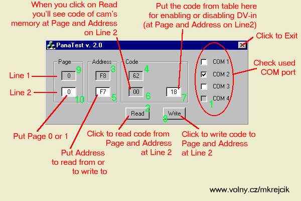
4. Check Com port which you are using (1) and click on Read button (2).
5. You should see:
1st line - Page "0" (9), Address "F8" (3) and code at this place of memory(4).
For older models only:
this can be used for identification of cam (62 is DA1 and so on) - compare with Table 1.
2nd line - Page "0" (at white field) (10) , Address "F7" (5) (at white field) and code at this place of memory (6).
For older models:
Compare with code at table 1, address F7 of your model: you can see if your cam has DV-in enable or disable.
For newer models:
Compare with code at table 2, if the code is the same as that at Table 2 - OK.
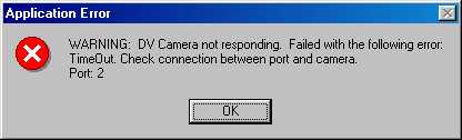
If the connection is wrong, you'll see message box and XX in code fields (4) (6).
6. For older models:
There are right Page ("0") and Address ("F7") for changing code on 2nd line. Put code for enabling DV-in (from Table 1 - e.g. DA1 - 00) to the white field above Write button (7) and click on Write (8). You can see the same code at field above button Read after successful writing to the cam.
If you have to change code at Address "30", click on Address "F7" (5) and change to "30". Click on Read. Compare with Table 1. And again: put code for enabling DV-in (from Table 1 - e.g. DA1 - EF) to the white field above Write button (7) and click on Write (8). You can see the same code at field above button Read after successful writing to the cam.
For newer models:
If you have to change code at Page "0", Address "DD", (all newer cams except DS11 and DS8 -from 3C to 2C for enabling DV-in) click on Address "F7" (5) and change to "DD". Page is the same as was - "0". Click on Read. You can see - "3C" for disabled and "2C" for enabled DV-in. Put right code for enabling DV-in (from Table 2 - "2C" for enabling) to the white field above Write button (7) and click on Write (8). You can see the same code at field above button Read after successful writing to the cam.
Now click on Page "0" (10) and change it to "1", click on Address "DD" (or "F7", if you have DS8 or DS11) and change to "97". Find the code for enabling your model (e.g. DS8 - "83", DS11 - "03") and put it to the white field above Write button (7) and click on Write (8). You can see the same code at field above button Read after successful writing to the cam.
Use only capital characters (A, B, C, D, E, F) or digits (0..9). If you put wrong character (i.e. ff, b8, ...), you'll get warning message and no code is written to cam. Allways make note of address and code before and after writing!
7. If you are finished, turn DVC off for no less then 5 sec.
If you need to disable DVin (for servicing) you can do it by the same process with codes for disabling.
WARNING!!!
Modification of cam's memory may result in lost of warranty.
Be careful. If you use wrong codes or addresses, you may damage your cam!
Close Panatest and turn off cam before connecting or disconnecting, you may damage your port!
DVin codes
Table 1 - older cams
If you don't have PanaTest v. 2 (unnecessary for older cams) ignore column Page
Model
|
Page
|
Address
|
Code En.
|
Code Dis.
|
Comment
|
DS77
|
0
|
F8
|
42
|
42
|
Identification
|
0
|
F7
|
01 or 81
|
19 or 99
|
||
0
|
30
|
23
|
33
|
||
DA1
|
0
|
F8
|
62
|
62
|
Identification
|
0
|
F7
|
00
|
18
|
||
0
|
30
|
EF
|
FF
|
||
DS33
|
0
|
F8
|
72
|
72
|
Identification
|
0
|
F7
|
01
|
19
|
||
0
|
30
|
23
|
33
|
||
EX1
|
0
|
F8
|
82
|
82
|
Identification
|
0
|
F7
|
01
|
19
|
||
0
|
30
|
23
|
33
|
||
DX100
|
0
|
F8
|
A2
|
A2
|
Identification
|
0
|
F7
|
00
|
18
|
||
DS5
|
0
|
F8
|
B2
|
B2
|
Identification
|
0
|
F7
|
00
|
18
|
||
DS1
|
0
|
F8
|
C2
|
C2
|
Identification
|
0
|
F7
|
A0
|
B8
|
Table 2 - New Cams
Use PanaTest v.2 for enabling these cams!
| Page | Comment | ||||
| DS99 | 0 | F7 | A0 | A0 | |
| 0 | DD | 2C | 3C | ||
| 1 | 97 | 02 | 12 | ||
| DS11 | 0 | F7 | 68 | 68 | |
| 1 | 97 | 03 | 13 | ||
| EX3 | 0 | F7 | A0 | A0 | |
| 0 | DD | 2C | 3C | ||
| 1 | 97 | 02 | 12 | ||
| DS8 | 0 | F7 | 68 | 68 | |
| 1 | 97 | 83 | 93 | ||
| DS35 | 0 | F7 | A0 | A0 | |
| 0 | DD | 2C | 3C | ||
| 1 | 97 | 02 | 12 | ||
| DS55 | 0 | F7 | A0 | A0 | |
| 0 | DD | 2C | 3C | ||
| 1 | 97 | 02 | 12 | ||
| DS15,DS25 | 0 | F7 | A0 | A0 | |
| 0 | DD | 2C | 3C | ||
| 1 | 97 | 07 | 17 |
Note:
Code en. = code for enabling (unlocking) DV-in
Code dis. = code for disabling (locking) DV-in
For older cams (Table 1):
Difference between codes of address F7 is allways 18h (in codes above):
Disable[F7] - Enable[F7] = 18h
Disable[30] - Enable[30] = 10h
For newer cams (Table 2):
Disable[0;DD] - Enable[0;DD] = 10h
Disable[1;97] - Enable[1;97] = 10h
Your List may be different from these above for different setting (or e.g. with/without cassette).
Note 1*:
Update 4.7.2000:
It isn't necessary to change code at address DD (page 0) for types DS8 and DS11, I got message that DV in of DS11 and DS8 works fine with unchanged code 3C at address DD. I got also information that EX3, DS35, DS55 and DS99 probably have the same codes but I still didn't get verifying about it.
Update 6.7.2000:
I got other messages that it is suffice to change only address [1;97] for all cams (except DS99 - I didn't got any message about it). But I recommend to use (and change} code 3C to 2C for DS35, DS55, DS99 and EX3.
Update 25.7.2000:
I have list of these unlocked cams:
DS8 - originally unlocked - bought in Singapoure, no change at page 0, address DD ([0;DD])
DS11 - unlocked by PanaDvin, no change at [0;DD]
EX3 - by PanaDvin, it has code 2C at [0;DD]
DS99 - one originally unlocked - bought in Australia and one unlocked by PanaDvin, the same as EX3
I have speculation about code at [0;DD] - correction of sumcheck (XOR). Again, I recommend to change code for newer cams except DS8 and DS11